- 您现在的位置:买卖IC网 > Sheet目录1214 > EVAL-ADE7878EBZ (Analog Devices Inc)BOARD EVAL FOR ADE7878
�� �
�
�Data� Sheet�
�ADE7854/ADE7858/ADE7868/ADE7878�
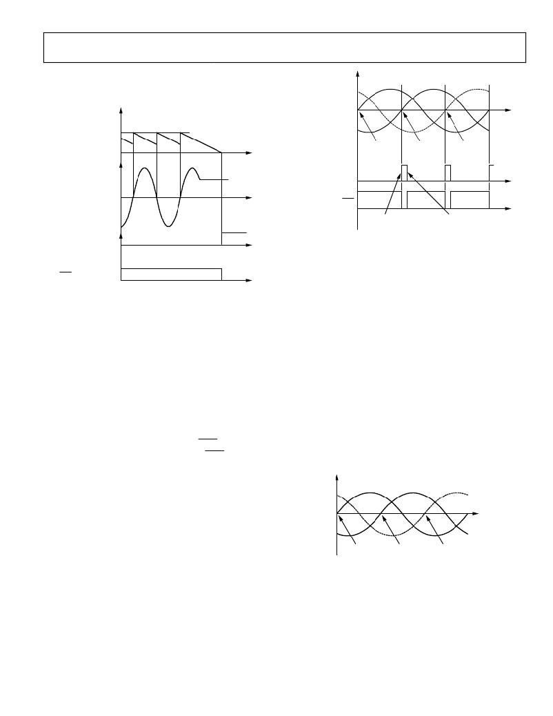
��detection� when� the� voltage� or� the� current� signal� stays� at� a� fixed�
�dc� level� for� more� than� 62.5� μs� ×� ZXTOUT� μs.�
�A,� B,� C� PHASE�
�PHASE� A�
�PHASE� C�
�PHASE� B�
�VOLTAGES� AFTER�
�16-BIT� INTERNAL�
�REGISTER� VALUE�
�ZXTOUT�
�LPF1�
�VOLTAGE�
�BIT� 19� (SEQERR)� IN�
�STATUS1� REGISTER�
�ZX� A�
�ZX� C�
�ZX� B�
�OR�
�CURRENT�
�SIGNAL�
�0V�
�IRQ1�
�STATUS1[19]� SET� TO� 1�
�STATUS1[19]� CANCELLED�
�BY� A� WRITE� TO� THE�
�STATUS1� REGISTER� WITH�
�ZXZOxy� FLAG� IN�
�STATUS1[31:0],� x� =� V,� A�
�y� =� A,� B,� C�
�IRQ1� INTERRUPT� PIN�
�Figure� 44.� Zero-Crossing� Timeout� Detection�
�Phase� Sequence� Detection�
�The� ADE7854� /� ADE7858� /� ADE7868� /� ADE7878� have� on-chip�
�phase� sequence� error� detection� circuits.� This� detection� works�
�on� phase� voltages� and� considers� only� the� zero� crossings�
�determined� by� their� negative-to-positive� transitions.� The� regular�
�succession� of� these� zero-crossing� events� is� Phase� A� followed� by�
�Phase� B� followed� by� Phase� C� (see� Figure� 46).� If� the� sequence� of�
�zero-crossing� events� is,� instead,� Phase� A� followed� by� Phase� C�
�followed� by� Phase� B,� then� Bit� 19� (SEQERR)� in� the� STATUS1�
�register� is� set.�
�If� Bit� 19� (SEQERR)� in� the� MASK1� register� is� set� to� 1� and� a�
�phase� sequence� error� event� is� triggered,� the� IRQ1� interrupt� pin�
�is� driven� low.� The� status� bit� is� cleared� and� the� IRQ1� pin� is� set�
�high� by� writing� to� the� STATUS1� register� with� the� Status� Bit� 19�
�(SEQERR)� set� to� 1.�
�The� phase� sequence� error� detection� circuit� is� functional� only�
�when� the� ADE78xx� is� connected� in� a� 3-phase,� 4-wire,� three� voltage�
�sensors� configuration� (Bits[5:4],� CONSEL[1:0]� in� the� ACCMODE�
�register,� set� to� 00).� In� all� other� configurations,� only� two� voltage�
�sensors� are� used;� therefore,� it� is� not� recommended� to� use� the�
�SEQERR� BIT� SET�
�Figure� 45.� SEQERR� Bit� Set� to� 1� When� Phase� A� Voltage� Is� Followed� by�
�Phase� C� Voltage�
�Once� a� phase� sequence� error� has� been� detected,� the� time�
�measurement� between� various� phase� voltages� (see� the� Time�
��phase� voltage� should� be� considered� with� another� phase� current�
�in� the� computational� datapath.� Bits[9:8]� (VTOIA[1:0]),� Bits[11:10]�
�(VTOIB[1:0]),� and� Bits[13:12]� (VTOIC[1:0])� in� the� CONFIG�
�register� can� be� used� to� direct� one� phase� voltage� to� the� datapath�
��section� for� details.�
�Time� Interval� Between� Phases�
�The� ADE7854� /� ADE7858� /� ADE7868� /� ADE7878� have� the� capa-�
�bility� to� measure� the� time� delay� between� phase� voltages,� between�
�phase� currents,� or� between� voltages� and� currents� of� the� same�
�phase.� The� negative-to-positive� transitions� identified� by� the� zero-�
�crossing� detection� circuit� are� used� as� start� and� stop� measuring�
�points.� Only� one� set� of� such� measurements� is� available� at� one� time,�
�based� on� Bits[10:9]� (ANGLESEL[1:0])� in� the� COMPMODE�
�register.�
�PHASE� A� PHASE� B� PHASE� C�
�detection� circuit.� In� these� cases,� use� the� time� intervals� between�
�ZX� A�
�ZX� B�
�ZX� C�
�phase� voltages� to� analyze� the� phase� sequence� (see� the� Time�
���followed� by� Phase� B� voltage� but� by� Phase� C� voltage.� Every� time�
�a� negative-to-positive� zero� crossing� occurs,� Bit� 19� (SEQERR)� in�
�the� STATUS1� register� is� set� to� 1� because� such� zero� crossings� on�
�Phase� C,� Phase� B,� or� Phase� A� cannot� come� after� zero� crossings�
�from� Phase� A,� Phase� C,� or� respectively,� Phase� B� zero� crossings.�
�Figure� 46.� Regular� Succession� of� Phase� A,� Phase� B,� and� Phase� C�
�When� the� ANGLESEL[1:0]� bits� are� set� to� 00,� the� default� value,�
�the� delays� between� voltages� and� currents� on� the� same� phase� are�
�measured.� The� delay� between� Phase� A� voltage� and� Phase� A�
�current� is� stored� in� the� 16-bit� unsigned� ANGLE0� register� (see�
��and� currents� on� Phase� B� and� Phase� C� are� stored� in� the� ANGLE1�
�and� ANGLE2� registers,� respectively.�
�Rev.� H� |� Page� 35� of� 100�
�发布紧急采购,3分钟左右您将得到回复。
相关PDF资料
EVAL-ADE7880EBZ
BOARD EVAL FOR ADE7880
EVAL-ADE7953EBZ
BOARD EVAL FOR ADE7953
EVAL-ADF4002EBZ1
BOARD EVAL FOR ADF4002
EVAL-ADG788EBZ
BOARD EVALUATION FOR ADG788
EVAL-ADM1021AEB
BOARD EVAL FOR ADM1021
EVAL-ADM1023EB
BOARD EVAL FOR ADM1023
EVAL-ADM1031EB
BOARD EVAL FOR ADM1031
EVAL-ADM1062TQEBZ
BOARD EVALUATION FOR ADM1062TQ
相关代理商/技术参数
EVAL-ADE7880EBZ
功能描述:BOARD EVAL FOR ADE7880 RoHS:是 类别:编程器,开发系统 >> 评估演示板和套件 系列:* 产品培训模块:Obsolescence Mitigation Program 标准包装:1 系列:- 主要目的:电源管理,电池充电器 嵌入式:否 已用 IC / 零件:MAX8903A 主要属性:1 芯锂离子电池 次要属性:状态 LED 已供物品:板
EVAL-ADE7880EBZ
制造商:Analog Devices 功能描述:ADE7880, ENERGY METER, 3 PH, SPI, I2C, E
EVAL-ADE7913EBZ
制造商:AD 制造商全称:Analog Devices 功能描述:3-Channel, Isolated, Sigma-Delta ADC with SPI
EVAL-ADE7953EBZ
功能描述:BOARD EVAL FOR ADE7953 RoHS:是 类别:编程器,开发系统 >> 评估演示板和套件 系列:- 标准包装:1 系列:PSoC® 主要目的:电源管理,热管理 嵌入式:- 已用 IC / 零件:- 主要属性:- 次要属性:- 已供物品:板,CD,电源
EVAL-ADF4001EBZ2
制造商:Analog Devices 功能描述:Evaluation Board For Pll Frequency Synthesizer 制造商:Analog Devices 功能描述:ADF4001 PLL SYNTHESIZER EVAL BOARD
EVAL-ADF4002EB1
制造商:Analog Devices 功能描述:EVAL BOARD - Bulk
EVAL-ADF4002EBZ1
功能描述:BOARD EVAL FOR ADF4002 RoHS:是 类别:编程器,开发系统 >> 评估演示板和套件 系列:- 产品培训模块:Obsolescence Mitigation Program 标准包装:1 系列:- 主要目的:电源管理,电池充电器 嵌入式:否 已用 IC / 零件:MAX8903A 主要属性:1 芯锂离子电池 次要属性:状态 LED 已供物品:板
EVAL-ADF4007EBZ1
功能描述:BOARD EVALUATION FOR ADF4007EB1 RoHS:是 类别:编程器,开发系统 >> 评估演示板和套件 系列:- 标准包装:1 系列:PSoC® 主要目的:电源管理,热管理 嵌入式:- 已用 IC / 零件:- 主要属性:- 次要属性:- 已供物品:板,CD,电源